48 Results
View results:
Sort by:

This example shows you how to quickly determine the buoyancy or the uplift limit state of a vessel in RFEM.

CFD calculations are in general very complex. An accurate calculation of wind flow around complicated structures is very demanding on time and computational costs. In many civil engineering applications, high accuracy is not needed and our CFD program RWIND 2 enables in such cases to simplify the model of a structure and reduce the costs significantly. In this article, some questions about the simplification are answered.

In order to be able to carry out a pushover analysis, it is necessary to transform the determined capacity curve into a simplified form. The N2 method is described in Eurocode EN 1998. This article should help to explain what a bilinearization according to the N2 method involves.

The Geotechnical Analysis add-on provides RFEM with additional specific soil material models that are able to suitably represent complex soil material behavior. This technical article is an introduction to show how the stress-dependent stiffness of soil material models can be determined.

Both the determination of natural vibrations and the response spectrum analysis are always performed on a linear system. If nonlinearities exist in the system, they are linearized and thus not taken into account. They are caused by, for example, tension members, nonlinear supports, or nonlinear hinges. This article shows how you can handle them in a dynamic analysis.

The events of recent years remind us of the importance of earthquake engineering in seismic regions. For you as an engineer, the design of structures in earthquake-prone areas is a constant trade-off between economic efficiency – the financial possibilities – and structural safety. If a collapse is inevitable, engineers must estimate how it will affect the structure. This article aims to provide you with an option on how to perform this estimation.

This article discusses the results of the geotechnical analysis and their graphical and tabular display in the RFEM 6 program.

Given that realistic determination of the soil conditions significantly influences the quality of the structural analysis of buildings, the Geotechnical Analysis add-on is offered in RFEM 6 to determine the soil body to be analyzed.
The way to provide data obtained from field tests in the add-on and use the properties from soil samples to determine the soil massifs of interest was discussed in Knowledge Base article “Creation of the Soil Body from Soil Samples in RFEM 6”. This article, on the other hand, will discuss the procedure to calculate settlements and soil pressures for a reinforced concrete building.

The quality of the structural analysis of buildings is significantly improved when the soil conditions are considered as realistically as possible. In RFEM 6, you can realistically determine the soil body to be analyzed with the help of the Geotechnical Analysis add-on. This add-on can be activated in the model’s Base Data as shown in Image 01.

With the release of the structural analysis programs RFEM 6, RSTAB 9, RSECTION 1, and RWIND 2, Dlubal Software introduces a new generation of structural analysis programs. True to the motto "Structural analysis that is fun ...", the program provides users with universal tools with which they can meet all the requirements in structural engineering. Find out more about the latest developments at Dlubal Software in this article.

Imperfections in construction engineering are associated with production-related deviation of structural components from their ideal shape. They are often used in a calculation to determine the equilibrium of forces for structural components on a deformed system.

In the age of BIM, data exchange between the various disciplines of structural engineering is becoming increasingly important. Since each software has its own specifications with regard to the description of cross-sections and materials, RFEM and RSTAB offer a conversion table (mapping file).
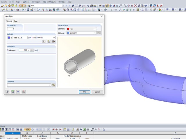
It may become necessary to analyze pipe cross‑sections as surface models in plant engineering in particular, but also when analyzing details of structural systems. For this purpose, RFEM offers the option to create pipe cross‑sections automatically by means of a line.

Before creating a structural model, every user gives thought to the boundary parameters of the system and how best to represent the model. Special attention should be paid to the orientation of the global coordinate system. In engineering, the global Z‑axis is usually oriented downwards (in the direction of the dead load), while it tends to be upwards in architecture. These differences can often lead to complications during modeling; for example, when you replace global models or DXF layers.

If the geometry of a surface for which you must remove some of the existing boundary lines changes subsequently, you do not need to redefine the surface.

In the RF-/FOUNDATION Pro add-on module, you can select the automatic dimensioning of the foundation plate geometry. In the dialog box for the design parameters of the foundation plate, you can, for example, specify the increment for the increase of the base area and the foundation plate thickness. You can also automatically increase the covering for a stabilizing effect of the geotechnical designs.
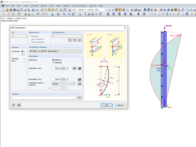
In the world of construction engineering, the word "imperfections" has a specific meaning. In general, it describes the incompleteness of a structure or the deviation of a structural component from an ideal shape caused by the production.
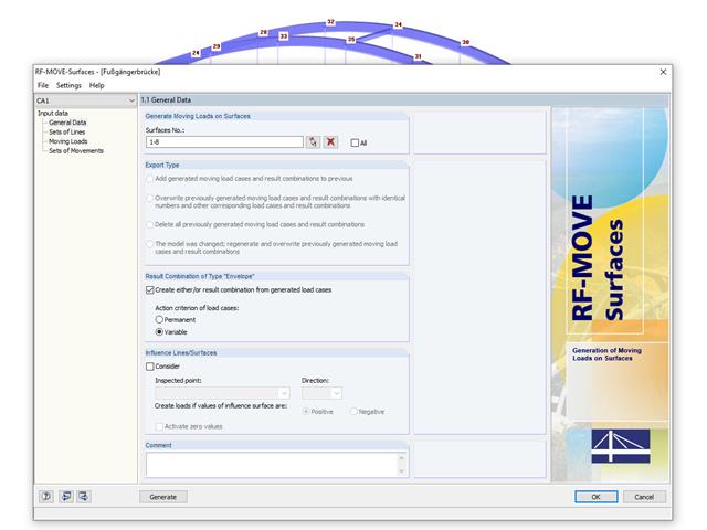
RF-MOVE Surfaces facilitates the generation of load cases from different positions of moving loads. Based on the load positions of the moving load, the program generates separate load cases for RFEM 5. Optionally, an enveloping result combination of all load positions is created.
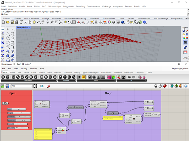
"A good tool is half the job done": This proverb could be applied equally to the software industry. The more a program is task-tailored, the more efficiently the tasks can be solved. The variety and complexity of today's problems, especially in structural engineering, require specifically tailored solutions. Creating your own programs by means of textual programming requires in-depth knowledge and a great ability to abstract. Understandably, only very few engineering offices face this challenge. For this reason, there are additional software solutions providing the user with a visual development environment.
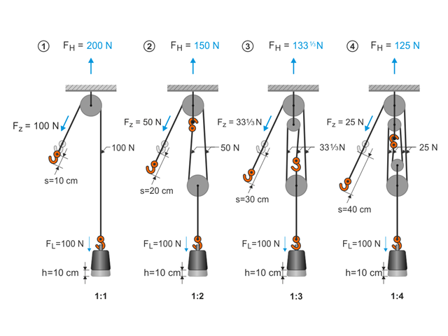
This article describes the basic principles and modeling approaches of pulley systems in RFEM.

The elastic deformations of a structural component due to a load are based on Hooke's law, which describes a linear stress-strain relation. They are reversible: After the relief, the component returns to its original shape. However, plastic deformations lead to irreversible deformations. The plastic strains are usually considerably larger than the elastic deformations. For plastic stresses of ductile materials such as steel, yielding effects occur where the increase in deformation is accompanied by hardening. They lead to permanent deformations - and in extreme cases to the destruction of the structural component.

The European standard EN 1993-1-8, Section 4.5.3.3. provides the user with a simplified method for the ultimate limit state design of fillet welds. According to the standard, the design is fulfilled if the design value of the resultant acting on the fillet weld area is smaller than the design value of the weld's load-bearing capacity. Thus, if you want to dimension the weld for a surface model, you will be faced with a variety of results due to the nature of FEM calculations. Therefore, we show in the following text how to determine the force components from the model.
The building and construction industry is increasingly digitized. Structural engineers, a smaller group in the construction industry, are not always considered to be engineers who follow the latest trends immediately. There is often good reason for this. Many consider this to be the reason that topics such as utilizing the BIM method are not yet the standard in structural engineering. However, the past few years have shown that a process of rethinking has begun, and new digital trends are being picked up and applied.

Both the determination of natural vibrations and the response spectrum analysis are always performed on a linear system. If nonlinearities exist in the system, they are linearized and thus not taken into account. Straight tension members are very often used in practice. This article will show how you can display them approximately correctly in a dynamic analysis.
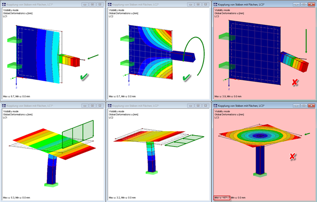
Pay particular attention to the connection points of members and surfaces when you deal with mixed systems, because not all internal forces can always be transferred without difficulty at the coupling location.
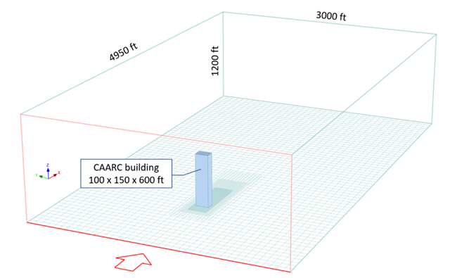
The following study compares the wind pressure on a tall building obtained by RWIND Simulation with the results published by Dagnew et al. at the 11th Americas Conference on Wind Engineering in June, 2009. In this paper, the Commonwealth Advisory Aeronautical Council (CAARC) building is used as a model, and the results of several different numerical methods are compared with experimental data obtained from wind tunnels.
.png?mw=640&hash=1be9a846b1f57190540c7fc7f46f44cd40ab7029)
The calculation of structures based on digital twins is becoming an everyday task in the engineering office. If a digital building model already exists, you want to continue to use the information contained in it as seamlessly as possible. This states extensive requirements with regard to modeling and interfaces for BIM-compatible structural analysis software.

DIN EN 1998-1 with the National Annex DIN EN 1998-1/NA specifies how to determine seismic loads. The standard applies to structural engineering in seismic areas.
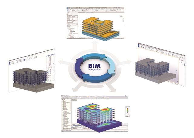
Building Information Modeling is making headlines in building design. While some engineers only use BIM methods for planning, others are dealing with this topic for the first time or rarely have time for it in their daily working routine. However, one topic seems the most important in structural engineering: How can structural engineers benefit from BIM?
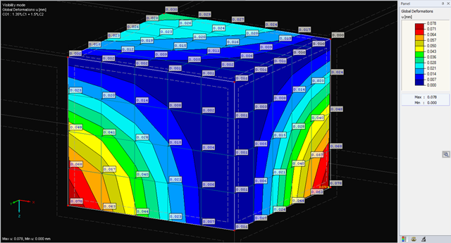
The deformations of the FE nodes are always the first result of an FE calculation. It is possible to calculate strains, internal forces, and stresses based on these deformations and the stiffness of the elements.